10 Key Differences Between Creep and Fatigue Damage
- matintegrity
- Aug 27, 2023
- 3 min read
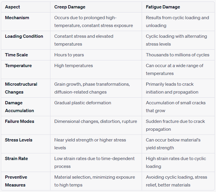
Creep damage and fatigue damage are two distinct mechanisms of material degradation that occur under different conditions and have different effects on the mechanical properties of materials.
Here are 10 key differences between creep damage and fatigue damage including examples:

Mechanism:
Creep Damage: Creep damage occurs due to the prolonged exposure of a material to high temperatures and constant mechanical stress, causing it to deform over time.
Fatigue Damage: Fatigue damage results from cyclic loading and unloading of a material, causing microcracks to form and propagate, ultimately leading to failure.
Loading Condition:
Creep Damage: It occurs under constant stress and elevated temperatures, often in situations where a material is subject to long-term loading.
Fatigue Damage: It occurs under cyclic loading, which involves alternating stress levels, even if the stress magnitudes are well below the material's ultimate strength.
Time Scale:
Creep Damage: It occurs over an extended period, typically hours, days, or even years.
Fatigue Damage: It occurs over a shorter period compared to creep, typically thousands to millions of cycles.
Temperature:
Creep Damage: Higher temperatures are usually required for creep damage to be significant, as it involves thermally activated processes.
Fatigue Damage: Fatigue damage can occur at a wide range of temperatures, including room temperature.
Microstructural Changes:
Creep Damage: Creep can lead to grain growth, phase transformations, and diffusion-related changes in the material's microstructure.
Fatigue Damage: Fatigue primarily results in crack initiation and propagation, leading to localized damage around stress concentration points.
Damage Accumulation:
Creep Damage: It involves gradual plastic deformation, where the material continues to deform even without the application of external loads.
Fatigue Damage: It involves the accumulation of small cracks that grow with each loading cycle until they reach a critical size, causing failure.
Failure Modes:
Creep Damage: Creep can lead to dimensional changes, distortion, and eventual rupture of the material.
Fatigue Damage: Fatigue failure is often characterized by sudden fracture due to the propagation of existing cracks.
Stress Levels:
Creep Damage: Creep damage typically occurs at stress levels close to the material's yield strength or at higher stress levels.
Fatigue Damage: Fatigue damage can occur at stress levels well below the material's yield strength.
Strain Rate:
Creep Damage: Creep involves low strain rates, as it's a time-dependent process.
Fatigue Damage: Fatigue involves high strain rates due to the cyclic loading.
Preventive Measures:
Creep Damage: Preventing creep damage often involves selecting materials with suitable high-temperature properties and designing components to minimize exposure to elevated temperatures and constant stresses.
Fatigue Damage: Preventing fatigue damage involves avoiding unnecessary cyclic loading, introducing stress-relieving features, and using materials with good fatigue resistance.
Creep Damage Example:
Imagine a high-temperature steam pipe used in a power plant. The pipe is constantly exposed to high temperatures and is under a constant load due to the pressure of the steam flowing through it. Over a period of years, the material of the pipe begins to experience creep damage. As a result, the pipe slowly starts to deform, causing dimensional changes and stress concentrations at specific points. Eventually, the material weakens to the point where it can no longer withstand the pressure and temperature, leading to a rupture in the pipe, releasing steam and potentially causing significant damage to the surrounding equipment.

Fatigue Damage Example:
Consider an industrial piping system where a metal pipe is connected to a nozzle, and the system experiences constant vibrations due to machinery operation. Over time, these vibrations create cyclic stresses at the junction between the pipe and the nozzle. Microscopic cracks initiate at this stress concentration point and gradually propagate with each vibration cycle. As the cracks grow, they weaken the material. Eventually, after a certain number of vibration cycles, the cracks coalesce, causing the pipe nozzle to fail suddenly due to fatigue, leading to leakage or even rupture of the system.


Comments